mptcptrace demo, experiment four
This is the fourth post of a series of five. Context is presented in the first post. The second post is here. The third post is here.
Fourth experiment
| Green at 0s: |
|
|---|---|
| Green at 5s: |
|
| Green at 15s: |
|
| Red at 0: |
|
| Red at 15: |
|
| Client: |
|
In this fourth experiment, we change the loss rate of the red path to 1% after 15 seconds.
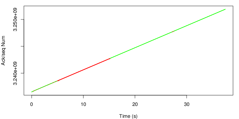
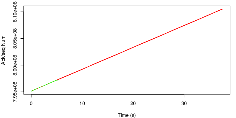
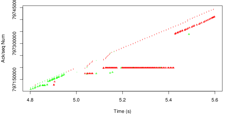
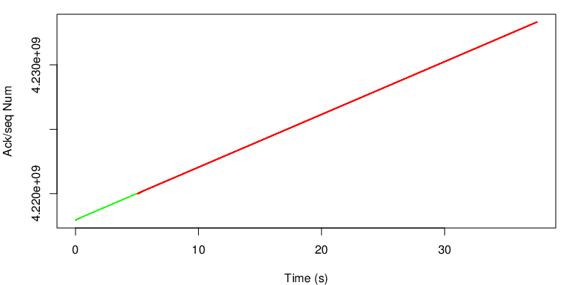
Again we take a look at the evolution of the sequence number.
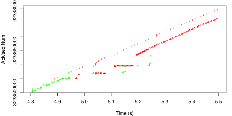
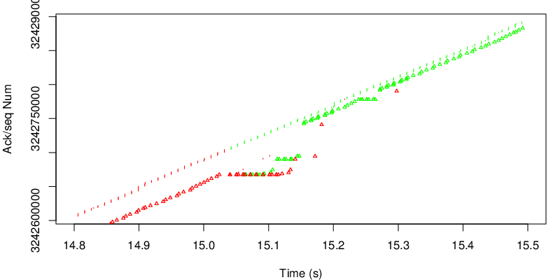
In this case however we can see the shift after 15 seconds. Because the red link become lossy after 15 seconds, the congestion window of the red subflow shrinks and MPTCP needs to send data again on the green subflow if the congestion window of the red subflow becomes too small to sustain the application rate. Because MPTCP now sends a little bit of traffic on the green subflow, it realises that the green subflow has changed and has now a lower delay and a lower loss rate. As a consequence the green subflow will open the congestion window again and will have a large enough congestion window to sustain the application rate.
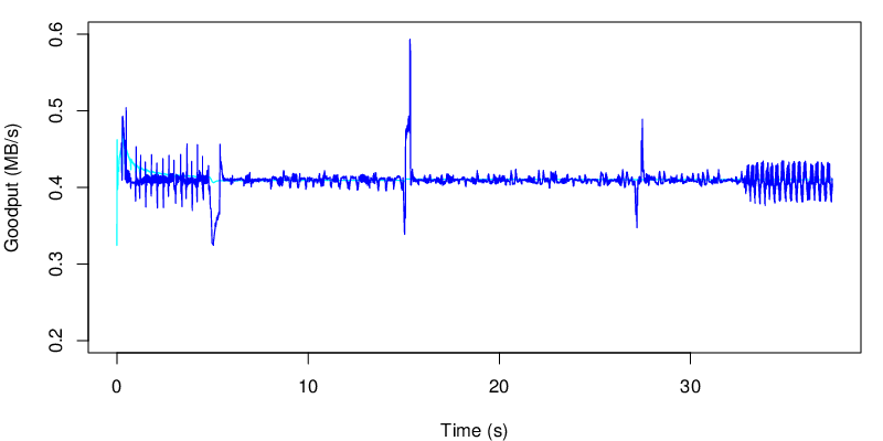
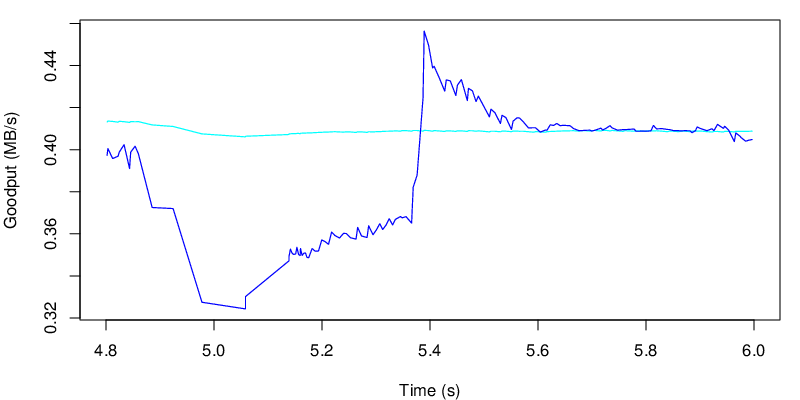
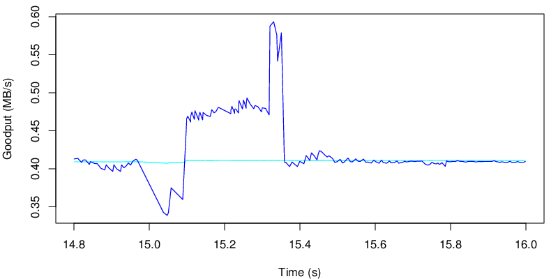
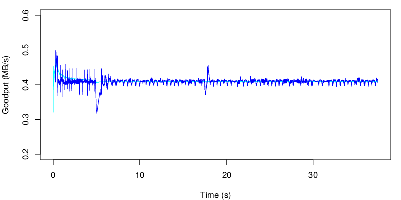
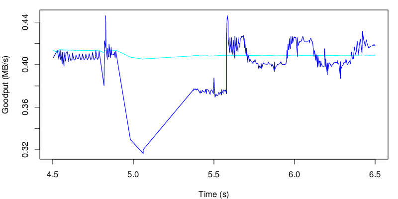
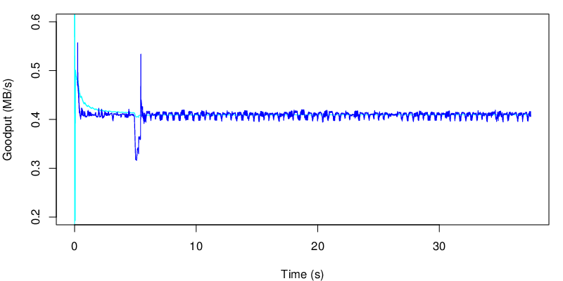
If we take a look at the evolution of the goodput, we see the two shifts at 5s and at 15s
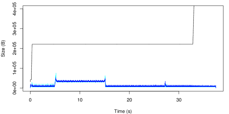
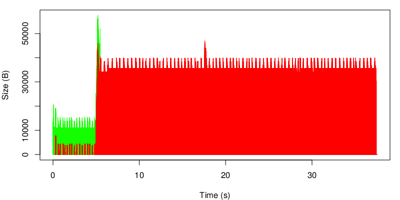
The evolution of the MTPCP unacked data is shown below :
We can see the change after 15s and that we use less of the receiver window after 15 seconds… In this case, because the red link is lossy, we consume less of the receive window. In our case the receive window is big enough anyway, but we would have different results if the window were smaller. We could reduce the window size by reducing the rmem but this for an other experiment.
Again we can look at the evolution of the unacked data at the TCP level
again we observe the shift after 15 seconds.
mptcptrace demo, experiment three
This is the third post of a series of five. Context is presented in the first post. The second post is here.
Third experiment
| Green at 0s: |
|
|---|---|
| Green at 5s: |
|
| Green at 15s: |
|
| Red: |
|
| Client: |
|
In this third scenario, the green link become lossless again after 15 seconds and its delay comes back to 10ms.
Again let’s see the evolution of the sequence numbers.
We can observer the same shift as the previous experiment from the green path to the red path after 5 seconds (see below). However, quite surprisingly, we can not see any shift after 15 seconds. Due to the many losses and the high delay between 5 and 15 on the green path, the green path may have a small congestion window and still have the same estimation of the RTT because no new traffic has been sent over the green subflow. No traffic has been pushed on the green subflow by MPTCP, because the red subflow, even though it has a longer delay, can still sustain the application rate. In conclusion, because MPTCP never probes the green subflow, it can not get any idea that this subflow could now be better.
We can also take a look the goodput. We see the same perturbation at 5 second that we saw on the previous experiment. And we don’t see any any change around 15 seconds. It’s normal because MPTCP does not come back on the green subflow.
Again the zoom shows similarities with the previous experiment.
We can also take a look at the amount of data that is not yet acked from the perspective of the sender.
On this figure, the black line shows the evolution of the receive window announced by the receiver. The cyan line shows the amount of data that is not MPTCP-acked while the blue line shows the sum of data that is not TCP acked. If the blue line and the cyan line do not stick, this means that that segments arrive out of order (from the MPTCP sequence number view point) at the receiver
We can also look at the evolution of the tcp unacked data by subflow.
This graph shows the evolution of the unacked data at the TCP layer. We can observe that MPTCP either choose one path or the other but hardly never choose to use both at the same time. On this graph we can also observe the consequence of a longer delay on the red path : the amount of data on flight is higher.
mptcptrace demo, experiment two
This is the second post of a series of five. Context is presented in the first post.
Second experiment
| Green at 0s: |
|
|---|---|
| Green at 5s: |
|
| Red: |
|
| Client: |
|
In this scenario, we change delay and the loss rate of the green link after 5 seconds.
Just like we did for the first experiment, we take a look at the ack/seq graph.
As expected, we see the shift from the green path to the red path after 5 sec. We will now take a closer look to what happens around 5 seconds, when the delay and the loss rate rise.
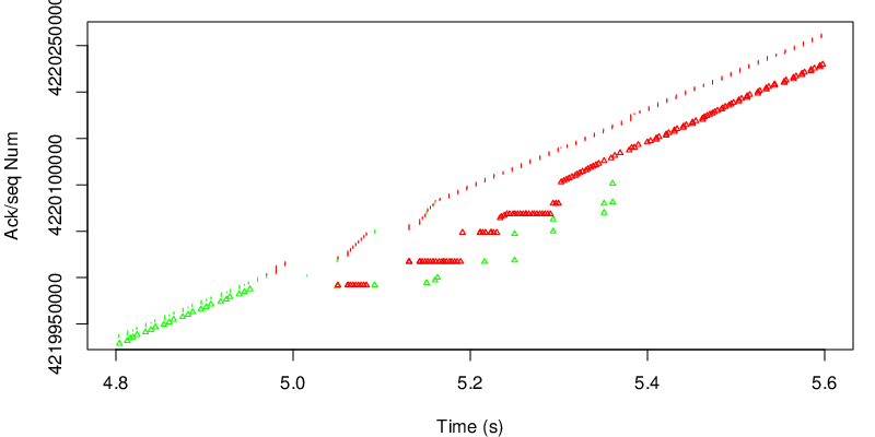
Because of the loss, the congestion window of the green subflow starts to shrink. As a consequence, MPTCP starts to send segments over the red subflow because there is not enough space in the green congestion window to sustain the rate. The spacing between the green segments and green triangle is different than the spacing between the red segments and the red triangles. This reflects the different RTT on the green subflow and on the red subflow. Because the green link is lossy and has a longer delay, we observe duplicate acks from the red link because we miss some segments sent on the green link at the receiver. However on the red link, even if we have a higher delay, we don’t have many losses. This leads to jump in acks during the transition. We can see the stair shape.
As we did for the previous experiment, we now take a look at the evolution of the goodput.
We see the transition after 5 seconds on the blue line. The consequences over the cyan line is however quite small. But let’s zoom a bit on this specific event.
As we can see after five seconds there is a drop in the “instantaneous” goodput, however this change does not really last enough time to have an impact on the average goodput. If the application is sensitive to goodput variation this may be an issue. If the application is not, the user should barely see the difference.
With synproxy, the middlebox can be on the server itself
Multipath TCP works by adding the new TCP options defined in RFC 6824 in all TCP segments. A Multipath TCP connection always starts with a SYN segment that contains the MP_CAPABLE option. To use benefit from Multipath TCP, both the clients and the server must be upgraded with an operating system that supports Multipath TCP. With such a kernel on the client and the servers, Multipath TCP should be used for all connections between the two hosts. This is true provided that there are no middleboxes on the path between the client and the server.
A user of the Multipath TCP implementation in the Linux kernel recently reported problems on using Multipath TCP on a server. During the discussion, it appeared that a possible source of problems could be the synproxy module that is part of recent iptables implementations. synproxy, as described in a RedHat blog post can be used to mitigate denial of service attacks on TCP by filtering the SYN segments. This module could be installed by default on your server or could have been enabled by the system administrators. If you plan to use Multipath TCP on the server, you need to disable it because synproxy does not currently support Multipath TCP and will discard the SYN segments that contain the unknown MP_CAPABLE option. In this case, the middlebox that breaks Multipath TCP resides on the Multipath TCP enabled server…
